Hydra
 |
How to use this document:
- Use the Introduction to familiarize yourself with the technical terms used in the content.
- Start with the Interface section to help you find your way around.
- Learn about the elements of your mission planning by visiting the Mission Components section.
- Wherever you see → Usage , click on it to dig deeper in how to use the controls.
Contents
- 1 Important Safety Instructions
- 2 Introduction
- 3 User Interface
- 4 Components of a mission
- 5 Creating a new mission
- 6 About the Tool Palette
- 7 Arena Map
- 8 Markers
- 9 Rulers
- 10 No-fly Zones
- 11 Routes
- 12 Scripts
- 13 Robot & Simulator Operation
- 14 Robot telemetry
- 15 Scenario Operation
- 16 Mission Planner Settings
- 17 Equipment Settings
- 18 Robot Communication Setup
Important Safety Instructions
WARNING: THIS PRODUCT SHOULD ONLY BE OPERATED BY TRAINED PERSONNEL. MAINTAIN SAFE DISTANCE BETWEEN ROBOTS AND PEOPLE OR PROPERTY. ALWAYS OPERATE WITHIN VISUAL LINE-OF-SIGHT.
- Read and understand this instruction manual before using.
- Do not expose the unit to rain or drive the unit through water.
- Disconnect battery before repairing or servicing the unit.
- Do not touch or short circuit exposed electrical connections.
- Do not unplug battery connections by pulling on wires. Only pull connector housings.
- Do not operate unit in crowded environments.
- Place barriers between people and unit to reduce the risk of injury.
- Dispose of batteries in environmentally appropriate manner.
- Do not discharge weapons directly at unit.
ALL GUNS ARE ALWAYS LOADED. NEVER POINT YOUR MUZZLE AT ANYTHING YOU DO NOT WISH TO DESTROY. KEEP YOUR FINGER OFF THE TRIGGER UNTIL YOUR SIGHTS ARE ON THE TARGET. ALWAYS BE SURE OF YOUR TARGET AND WHAT IS BEYOND.
Introduction
System
Hydra Mission Planner is a software/hardware suite to allow your targeting robots to execute controlled complex motions over time, repeatedly.
It is designed to be simple to use without expert knowledge of navigation and robotics.
The only prerequisite is to make sure your range is covered be a WIFI signal that Hydra is going to use to communicate with the robot hardware → WIFI Setup .
Once you have WIFI, you can start Hydra Mission Planner and establish your range map by either using your address or longitude and latitude of your location.
The longitude and latitude can easily be gotten by using a map application such as Google, Bing, or Apple Maps. You can also use a handheld GPS or smartphone to find your current position.
The Mission Planner map will be cached once it has been downloaded from the web and no further internet connection is needed.
You can plan your missions by creating → Routes and → Scripts offline and then test them with → Simulations.
Later on the field, you can establish contact with the actual robot and assign the mission route or script at that time.
Once the mission is assigned and saved it stays with that robot until a new mission is created and assigned.
Geodesic Location
A geodesic location is a specific point on the earth's surface and is at the heart of the mission planner.
A location on a sphere (like the earth) are expressed as two angles:
- First, the latitude starts from the equator (0 degree) and ends up at a pole (90 degrees).
- In order to distinguish which pole, the north pole is a positive angle and the south pole is a negative angle.
- Second, the longitude starts at the Prime Meridian (0 degree at Greenwich, UK) and wraps to 180 degrees around the international time line.
- Here, again the direction west or east is indicated by the sign of the number where negative is west and positive goes east.

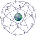
Global Position System
Hydra Mission Planner uses GPS (Global Position System) to locate the robot's position on your range.
Due to various factors such as satellite coverage, atmosphere, and hardware limitations you can expect, on the average,
an accuracy of 1 meter (3.2 feet) of your actual robot's location. When planning mission, please keep this in mind and
allow ample space between obstacles for your robots to move freely even when the GPS coverage is less then ideal.
The user interface does provide you helpful graphical information to show you if you might run into an obstacle
and you can check the state Global Position System by attaching a GPS unit to the base station. → How To
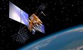
Satellite
Orbits


Waypoints are an important part of a successful navigation.
These are named points of interest that can be both a physical feature and/or simply a GPS location.
There are used to indicate the start, destination, and direction changes and when used together constitutes a route or path to navigate.
The connecting line between waypoints is a leg.
Legs can be straight as the crow flies or curved as part of a smooth route.

Orientation is the direction you are pointed at.
Orientation is based on true north expressed in degrees.
- 0° points to true north.
- 90° points east.
- 180° or -180° is south.
- 270° or -90° is west.
User Interface

1 Arena View

This is the main viewing area of the user interface.
The operational arena and surrounding area are shown as background.
On top of that graphic, all elements of the mission are superimposed.
These include no-fly zones, routes, scripts, rulers, markers, and current location of robots as icons.
![]() This compass graphic is purely decorative and indicates the map's orientation.
This compass graphic is purely decorative and indicates the map's orientation.
![]() This constellation graphic appears only when a GPS receiver is attached and active. → Setup
This constellation graphic appears only when a GPS receiver is attached and active. → Setup
Additional there are controls to help you navigate.
- Click
 to zoom into the map.
 - Click
 to zoom out of the map.
 - Click
 to reset the map to the midpoint of the map.
For trackpads, the computer's gestures to swipe move and pinch zoom the map can be used as well.
2 Tool Palette
This dockable strip of icons allows a tool to be selected. → Usage
3 Element List
This resizable area shows the list of elements that the selected tool represents.
Selecting the route tool, for instance, displays all routes of the mission in this list.
4 Global Controls
The controls in this area start/stop the mission .
5 Time Line
This shows the global timing of the mission as well as the timing of the currently editable script.
6 Popup View
Popup view displays scripts editors or robot telemetry based on which tool is active and the element selected.
7 Viewbar
The view controls what page is currently being displayed:
- Arena show the Arena View as well as undo/redo/save controls and the current time.
- Missions shows the mission creation/management page
- Settings displays the global settings of Hydra Mission Planner.
- Equipment display the current and archived equipment (robot) list and their configuration.
- About displays application information.
Clicking on the save control ![]() saves the current state of the mission.
saves the current state of the mission.
Clicking on the undo control ![]() will undo the previous action taken including any redo.
will undo the previous action taken including any redo.
Clicking on the redo control ![]() redoes the previous undo, effectively canceling the undo.
redoes the previous undo, effectively canceling the undo.
- NOTE: Undoable actions are recorded until memory is full. In practice, this will take a long time.
For convenience, the system clock's current time is displayed on the right side of the bar.
8 Arena Information Bar
Click the GPS control ![]() to record the base station's GPS receiver antenna at the reported location.
to record the base station's GPS receiver antenna at the reported location.
it also shows whether a GPS receiver has been attached and is actively receiving GPS location information.
Usage requires GPS receiver to be attached to the base station and actively reporting back the current GPS location. → Setup
Click the WIFI control ![]() to reset all communication channels to the robots on the field.
to reset all communication channels to the robots on the field.
Click the broadcast control ![]() to activate or deactivate the broadcast signal to automatically connect robots:
to activate or deactivate the broadcast signal to automatically connect robots:
 indicates active.
 indicates inactive.
This is useful, if you want to temporarily halt any communication and suspend operations for awhile without shutting down Hydra.
NOTE: Make sure to reset the communication after the broadcast has been deactivated. See WIFI control ![]() .
.
The current location and altitude at the mouse position as it hovers over the Arena View's map are shown following Lat/Lon/Alt:. → Definition
- The first number of the location set is the latitude (Lat).
- The second number is the longitude (Lon).
- The third and final number is the altitude from sea level (Alt).
The empty space after the location information is used for simple messages that arise during operations.
This may include state changes and error messages.
Components of a mission
 Arena Map
The arena map is the birds-eye view of the operational area in which the robot is operating. → Usage
 Markers
Markers are graphic indicators for locations of interest.
These include home locations of robots and the antenna location of the base station. → Usage
 Routes
Routes are paths used by the robot to travel from waypoint to waypoint. → Usage
 Scripts
One of the more powerful features of planning a mission is using a script to describe a unique motion per robot.
While routes give you basic motion from A to B with a specific speed, script allows you to stop, turn,
and vary the speed from waypoint to waypoint based on timing. → Usage
 No-fly zones
No-fly zones are areas where the robot are not allowed to travel to or through.
These include obstructions such as buildings and difficult terrains to traverse.→ Usage
 Rulers
This feature allows you to measure distances and orientation angle relative to true north. → Usage
 Robots
Devices are all robots, both online and offline, that are present in the current mission. → Usage
 Mission Files
Mission files are are used to store the current state of a mission.
Whenever Mission Planner saves a mission, it updates these suite of files to save the mission at that moment to be later restored.
They are saved in the operating system's documentation directory under "HydraMissions" directory.
Each mission has its own directory where it stores all necessary mission information.
- NOTE:
- While all files are human readable, it is NOT recommended to try editing them outside Mission Planner.
- They contain important information necessary for the correct function of a mission.
Creating a new mission
From Lat/Long
TDB
Address lookup
TDB
From a GPS unit
TDB
About the Tool Palette

Tool Interface
The Tool Palette lists all tools to create, manage, and edit all parts of a mission.
Click on the tool's icon, to pick the current tool.
Some tools have sub-tools indicated by a red triangle in the bottom-right corner of the icon.
Click on the tool icon and hold to pop out the list of sub-tools, move the mouse to the sub-tool, and select it.
Tool Tips
Positioning the mouse cursor over various controls and tool pallet icons will show a short description of the control's purpose.
Click and drag the mouse out of the icon's area to pop out the sub-tools.
Click on the sub-tool to activate it.
Drawing Element Visibility
Some Tools allow its graphic elements to viewable in the Arena View even if they are not active.
By design, an active tool always shows its graphic elements in the Arena View.
Click on the blue check box in the bottom left corner of the tool icon to show/hide the graphic.
Special Tool Functions
Double clicking selected tools will bring up dialogs for optional operations.
Tool Palette List
| Tool Selection |
Tool Name |
Tool Visibility |
Tool Double Click |
|---|---|---|---|
| Info Tool | No | No | |
| Map Tool → Usage | No | Edit Location and offset → Usage | |
| |
Marker Tool → Usage | Yes | No |
| |
Route Tool → Usage | Yes | No |
| |
Path Tool | Yes | No |
| |
Robot Tool | Yes | Create robot simulator |
| No-Fly Zone Creation → Usage | Yes | No | |
| |
No-Fly Zone Editing → Usage | Yes | No |
| |
Ruler Tool → Usage | Yes | No |
| |
Script Tool → Usage | Yes | Create script from route. → Usage |
Tool Palette Location
The Tool Palette is a dockable window and can be moved from its default location on the left side to any other side including top and bottom.
Click the title bar region on the top of the tool palette icons and simple drag it to its new location.
If you wish to make it a floating window, simply drag it away from any sides and release it.
Arena Map
The arena map is the mission's location satellite view used to pick locations for all mission elements.
It is centered around the mission's base location and consists of 1 or more tiles depending on coverage needs.
When a new mission is created, the satellite view is downloaded from the internet which necessitates a live connection.
Once the map tile(s) are downloaded, they are cached onto the computer's internal storage and used without an internet connection.
- Note: If the base location is modified, the satellite imagery will need to be downloaded again from the internet.
During download, you will see this graphic below, indicating a download is in progress.

Click the cancel button ![]() to stop the download.
to stop the download.
To resume download, double click on the Map Tool to bring up the Map Configuration Dialog.
Click the "Update" button.
Map Configuration

Double click on the Map Tool to bring up the above dialog to modify the map numerically.
Change the Latitude and Longitude of the Arena map center.
Change the Area tiles to change the map size and coverage.
Each map tile will cover an area of 150 by 150 meters, or 164 by 164 yards.
comfortably fitting three football fields side by side.
- Map area coverage is as follows each side:
- 1 Tile = 150 meters
- 9 Tiles = 450 meters
- 25 Tiles = 650 meters
- 49 Tiles = 1050 meters
Change the East and North Offset in meters to adjust for GPS inaccuracy.
Click "Update" to affect the changes.
- NOTE: The map will reload if the location and tiling have been modified.
Robot shifting
Select the robot shift tool ![]() to interactively shift the robot's position.
to interactively shift the robot's position.
Normally, this is not necessary and only used in extraordinary circumstances.
Map shifting
Select the shift tool ![]() to interactively shift the map off its center.
to interactively shift the map off its center.
This is a simple numerical offset of the graphic elements to adjust for GPS inaccuracy.
Normally, this is not necessary and only used in extraordinary circumstances.
Markers

Markers are used to indicate points of interest in the arena.
They also indicate special locations such as the base station's GPS antenna and home location for a robot to return to.
Markers are indicated by ![]() in the arena view and selecting a marker will show its name.
in the arena view and selecting a marker will show its name.
A special marker indicated by ![]() shows the location of the home position of a robot.
shows the location of the home position of a robot.
The optional GPS antenna location is shown with this ![]() graphic indication.
graphic indication.
Creating a marker
To add a marker, select the create marker icon ![]() in the tool palette.
in the tool palette.
Click on the arena map to place the new marker. The bottom tip will be the exact location.
Editing a marker
To move a marker, select the edit marker icon ![]() in the tool palette.
in the tool palette.
Click on the marker and move it to a new location.
Optional Base Station Marker
To indicate the base station's GPS antenna location, use the GPS icon ![]() from the
maker tool palette.
from the
maker tool palette.
Click on the map to create it, or click on the existing marker to move it.
NOTE: Only one antenna location is allowed.
Management

The markers location can be modified here in the element list.
"Lat" refers to the latitude while "Lon" indicates the longitude of the marker's location. → Definition
Renaming
Marker's name can be renamed by selecting the name and editing it.
Removing
To delete a marker, click on the delete icon ![]() .
.
Visibility
Click on the check box to the left of the name to show or hide the marker in the map view.
Locking
Click on the icon ![]() to lock or
to lock or ![]() to unlock the marker from being modified.
to unlock the marker from being modified.
Rulers

Creating a ruler
Click on the ruler icon ![]() to add a new distance ruler to the map.
to add a new distance ruler to the map.
In the arena view, click on the starting point of the measurement and drag the destination point.
The distance and orientation will be displayed in real time while the ruler is created.
Once the ruler is added, it will display its length in a fine print when unselected.
When selected, both distance and orientation are displayed.
- Hold the mouse while dragging to the destination point.
Editing a ruler
Click on the ruler edit icon ![]() to edit an existing ruler.
to edit an existing ruler.
Click on either end to reposition it, or click on the line connection the two ends to move the whole ruler.
Management
![]()
Renaming
A ruler can be renamed by selecting the name in the element list view to the right of the map view.
Removing
Click on the delete icon ![]() .
.
Visibility
Click on the check box to the left of the name to show or hide the ruler in the map view.
Locking
Click on the icon ![]() to lock or
to lock or ![]() to unlock the ruler from being modified.
to unlock the ruler from being modified.
No-fly Zones

Zones can be convex ![]() as well as concave
as well as concave ![]() and must have a minimum of 3 vertices
and must have a minimum of 3 vertices ![]() .
.
Zones cannot have holes ![]() or intersect
or intersect ![]() itself.
itself.
Creating a No-fly zone
Creating a no-fly zone can be done with a variety of shape tools.
Selecting the zone tool:
![]() creates a zone aligned along north-south and east-west.
creates a zone aligned along north-south and east-west.
![]() creates a rectangle using the third point to rotate it to an arbitrary direction.
creates a rectangle using the third point to rotate it to an arbitrary direction.
![]() creates a circular zone anchored at the first point and using the second point to specify the diameter.
creates a circular zone anchored at the first point and using the second point to specify the diameter.
![]() creates a circular zone using 3 points.
creates a circular zone using 3 points.
![]() creates a free-form zone with as many points as necessary to fit the area.
creates a free-form zone with as many points as necessary to fit the area.
- NOTE: Zones are either concave
 or convex
  and cannot intersect itself
  .
.
- NOTE: Zones are either concave
The first click establishes the first vertex.
While dragging around the mouse for the second click, the potential side of the zone is displayed in real time before setting down the next vertex.
- Do not hold the mouse while dragging.
- Just click, release, and move the mouse to new location.
- Repeat.
Each subsequent click will add another vertex until the first vertex is clicked, closing the zone and terminating the current zone creation.
At any time, the user may hit the return key to automatically close the zone and terminate the operation.
Hitting the delete/backspace key while in zone creation will remove the last vertex.
Arena Boundary Zone
The arena boundary serves as the outermost area of allowable robot movement usually restricted to the training ground.
NOTE: Only one arena boundary is allowed.
An arena boundary is created using this free-form tool ![]()
Editing a No-fly zone or Arena boundary zone
Existing no-fly zone can be edited using these:
![]() allows vertices to be moved and removed.
allows vertices to be moved and removed.
- Select a vertex by clicking on it or
- Select a side to select its end vertices.
- Hitting delete/backspace removes the selected vertices.
![]() moves the whole zone to a new location.
moves the whole zone to a new location.
Management
![]()
Renaming
The zone's name can be changed by selecting the name and editing it.
Removing
To delete a zone, click on the delete icon ![]() .
.
Visibility
Click on the check box to the left of the name to show or hide the zone in the map view.
Locking
Click on the icon ![]() to lock or
to lock or ![]() to unlock the zone from being modified.
to unlock the zone from being modified.
Routes

Routes are the named pathways that are used by robots to drive along.
They also are the basis for creating scripts governing the robots behavior and movement.
Elements of a route
Waypoints
A waypoint is a location where the route either begins, ends, or changes direction.
The first waypoint is the starting position. This is indicated by a square enclosing the location in the map view ![]() .
.
The last waypoint is the destination position. This is indicated by a triangle enclosing the location on the map view ![]() .
.
Waypoints in between are indicated by circle enclosing the location on the map view ![]() .
.
Legs

A leg is the connecting path between two waypoints.
An arrow on the leg midway between the two waypoints indicate the travel direction from the starting to the destination waypoint.
The number in small type at the midway of the leg is the leg's length in meters.
Confidence

The robot's accuracy in following the route may vary depending on GPS accuracy and terrain condition.
An area superimposed on the route with an adjustable width is shown to indicate worst case offset of the robot from the route.
This allows the operator to adjust the route around potential obstacles.
Looping
When a route is looped, the connecting leg between the starting and destination point is indicated by a dashed line.

Curved Paths
Routes can be either straight or smooth between waypoints.

Violations
Routes that start, end, or cross a no-fly zone or area boundary are indicated in red.
No-fly zones, and arena boundaries are used to indicate obstacles and dangerous areas where the robot is not allowed to roam.
Creating a route
Click on the Route Tool ![]() to activate the route tool.
to activate the route tool.
The first click creates the starting waypoint of the route with every subsequent click adding more waypoint.
- Do not hold the mouse while dragging.
- Just click, release, and move the mouse to new location.
- Repeat.
After the destination (last) waypoint has been creating, hitting the "Enter" will terminate the route creation and
allow for the next route to be created.
Hitting the delete or backspace key will remove the last waypoint created while creating the route.
It is possible to void the route by deleting the last waypoint until the starting waypoint is deleted as well.
While creating the route, an invalid path that crosses a No-fly zone will be be indicated by a color change to red.

When this happens you will also see a dashed line appear that will lead around the No-fly zone.

This is the shortest route around the obstacle and is computed automatically.

At this point, setting down a new waypoint at the mouse location will create a route using this automatically computed section.
It is entirely possible to create a route that will avoid many No-fly zones by simply creating the starting and destination waypoint only.
Moving waypoints
Select the route's edit tool ![]() to change the location of an waypoint on the route.
to change the location of an waypoint on the route.
Click on the waypoint and move it to a new location. Clicking on the leg between two waypoints will move both waypoints.
Hitting delete or backspace while the waypoint is highlighted will remove it.
Inserting waypoints
Select the route's insert tool ![]() allows a new waypoint to be added on a leg of a route.
allows a new waypoint to be added on a leg of a route.
While the mouse is hovering above the path between two waypoints, the potentially inserted waypoint is shown as a circle on the path.
Click the mouse will insert a new waypoint.
Translating a route
Select the route's move tool ![]() to translate (move) the entire path to a new location.
to translate (move) the entire path to a new location.
Click on any part of the route to move it.
Duplicating a route
Select the route's copy tool ![]() to duplicate a route.
to duplicate a route.
This tool allows quick creation of similar paths.
Click on the path to be duplicated and move it to a new location.
Management

Renaming
The zone's name can be changed by selecting the name and editing it.
Removing
To delete a zone, click on the delete icon ![]() .
.
Visibility
Click on the check box to the left of the name to show or hide the zone in the map view.
Locking
Click on the icon ![]() to lock or
to lock or ![]() to unlock the zone from being modified.
to unlock the zone from being modified.
Additional Controls
Click the check box next to "Closed Loop" to indicate a closed route with a leg connection the starting location and destination waypoint.
Click the check box next to "Smooth Path" for curved or straight legs between waypoints.
Click the check box next to "Confidence" to superimpose the confidence area of the route.
- The radius of confidence can be changed by editing the value. The confidence radius is in meters.
Scripts
A typical script is structured like this:
# Automatic script for path "Route G"
# NOTE: All scripts require a version

    version 1.0

#
# Path Specification
#

    waypoint WP_1 at 34.1043337, -117.7239717
    waypoint WP_2 at 34.1043255, -117.7237885
    waypoint WP_3 at 34.1041385, -117.7237898
    waypoint WP_5 at 34.1041590, -117.7238949
    waypoint WP_4 at 34.1042097, -117.7239816

#
# Move to home position of path
#

    move to waypoint WP_1 at 2.00 m/s

#
# Stop and turn to face first waypoint
#

    stop
    turn to waypoint WP_2 for 2.0 seconds

#
# Start mission on path
#

    move to waypoint WP_2 at 2.00 m/s
    stop
    turn to waypoint WP_3 for 2.0 seconds
    move to waypoint WP_3 at 2.00 m/s
    stop
    turn to waypoint WP_5 for 2.0 seconds
    move to waypoint WP_5 at 2.00 m/s
    move to waypoint WP_4 at 1.00 m/s
    move to waypoint WP_1 at 2.00 m/s

#
# Halt mission at last waypoint
#

    halt
A script consists of both executable and non-executable lines.
Non-executable lines are either comments that you can use to document or empty lines.
A comment line always starts with # (pound sign) followed by an optional line of text.
Empty lines are typically used for formatting purposes to easier read the script.
Executable lines have a single command with options that perform some kind of action.
Only one command per line is allowed.
Every command is terminated by a carriage return.
Command Set
| Command | Description | Usage |
|---|---|---|
| version | This is required as the first executable.
It indicates the version of the script for proper execution. |
version < float >
|
| waypoint | This command specifies a named waypoint.
Waypoints are destinations on the map as latitude, longitude.→ Definition |
waypoint < name > at < longitude >,< latitude >
|
| stop | Stop the robot with optional time until next command is executed. | stop
stop for < time > seconds
|
| halt | Stop the robot and terminate the script. | |
| turn | Turn the robot by either an angle or towards a waypoint. | turn < angle > for < time > seconds >
turn to waypoint < name > for < float > seconds
|
| move | Drive the robot at the specified speed towards its destination | move at < speed > m/s for < time > s
move to waypoint < name > at < speed > m/s
move to location < longitude >, < latitude > at < speed > m/s
move to < name > at < speed > m/s
|
Creating a Script
Scripts are created by double clicking the script tool.
You will be asked to specify an existing route or a blank script.

If no route is specified, a simple blank script is created without any commands.
If a route is specified, a fully functional script with the route's waypoints and appropriate commands to traverse the route.
This is the easiest way to create functional script.
Once the creation dialog is dismissed, the new script will appear in the script list.
You may change the name of the script in the script list by simply clicking on the name and editing it.
Editing a Script
Click on the edit icon ![]() to edit the script in the editor.
The editor pane is divided into three parts.
to edit the script in the editor.
The editor pane is divided into three parts.

The top line indicates the name of the script and shows the syntax check and close button.
The bottom line shows important messages.
Finally the middle part is the editor itself displaying the script for modification.
Each line of the script is numbered to the left of the script text.
This is useful in fixing syntax errors.
The editor uses color to tag correct syntax.
Any text that is gray indicates either a syntax error or optional words not necessary for the execution.
Cyan (bluish) lines are comments.
Purple words are commands and required keywords.
Yellow are numbers.
Click the check mark ![]() on the top line to verify the syntax of the script.
on the top line to verify the syntax of the script.
if the script is correct, the message "Script OK" will appear in the message line.
if the syntax is not correct, the message will indicate the line number and syntax problem followed by "Script Error" below.
To close the editor, click the close button ![]() .
.
Waypoints locations may be edited using the editor or, better yet, graphically on the map.
Each script is shown as a blue route.
Clicking on the waypoint of a script route and moving it will modify the script to record the new waypoint location.
The script is then automatically saved.
Timing Graph
Timing are edited using the timeline editor on the bottom of the main interface.
To show the timing graph, click on the timing edit icon ![]() of the script element.
of the script element.
![]()
The timing graph shows the script's timeline in a graphical way.
The horizontal dimension shows the time starting at zero while the vertical dimension represents the speed in meters per second.
The yellow line represents the speed of the robot in time.
The blue areas shows motion along waypoints at speed indicated by the yellow graph.
The green areas are rest time intervals where the robot is either stopping or turning.
The gray lines separating the rest and motion time intervals can be selected and dragged horizontally to change the time interval of the prior area.
These changes will be indicated in the script and automatically saved.
While changing the time interval of a motion (blue) region, you will notice that the script will correspond by changing the speed.
Increasing the time interval will drop the speed (slow down).
Decreasing the time interval will raise the speed (speed up). This is due to basic physics. While the motion distance stays the same,
the robot has to travel faster if the time to traverse is less. Otherwise, it has to slow down when the time to reach the end of that section is increased.
The speed of the robot can be manipulated as well by selecting the speed graph (yellow line) and modified by moving up or down.
When changing the speed, you will notice that the time interval is modified as well.
Timing is adjusted as the speed is changed since the distance traveled stays the same.
Editing Script Path
An active and selected script will show its path on the map.
You can interactively edit each waypoint by clicking on it and dragging it to a new location.
Simulating a script
Simulating a script is the same as simulating a robot.
Startup a robot simulation and set the robot's mission to the script.
Execute the robot's mission.
Management
![]()
The number to the right of the script name is the overall time in seconds it takes to execute the script's operations.
From the element view a script can be edited by clicking on the edit icon ![]() . → Usage
. → Usage
Clicking on the timing icon ![]() , activates the scripts timing in the timeline view. → Usage
, activates the scripts timing in the timeline view. → Usage
Renaming
The script's name can be changed by selecting the name and editing it.
Removing
To delete a script, click on the delete icon ![]() .
.
Visibility
Click on the check box to the left of the name to show or hide the script in the map view.
Locking
Click on the icon ![]() to lock or
to lock or ![]() to unlock the script from being modified.
to unlock the script from being modified.
Robot & Simulator Operation
Robots can be added manually for simulation, or by discovery after configuring a physical robot → Setup WIFI.
Once a robot has been added it will remain with the mission until removed from the robot element list.
Management
The robot element list shows all active and inactive robots.
Field robots will be become active automatically as long as they are powered and correctly configured to the base station's WIFI router.
An inactive robot is shown with their name and ID only, as well as controls to simulate or remove it from the list.
Any inactive robot can be simulated and mission reconfigured, even those that were discovered during a previous session.
To delete an inactive and non-simulated robot, click on the delete icon ![]() → Usage
→ Usage

While the robot's device is active or simulated, its current position will be reported using an icon and a heading indicator.
The robot's name and battery condition will be shown as a floating label when selected.
This label is always visible and connected to the robot's map position by a line even when the robot's position is offscreen.
A 2 meter radius safety zone is shown surrounding the robot's position.
Adding a Simulator
To manually add a robot, double-click the Robot Tool to show the following dialog:

Specify the name of the robot. Although the name does not need to be unique, it helps to find the device in the element list.
Specify the MAC address of the robot. This can be a the physical's robots MAC address or any type of text.
NOTE:
- The MAC address text must be unique from all other robots already in the mission planner for proper functioning.
- Physical robots already have unique MAC addresses and will be automatically added to the mission planner.
- Robots for simulation purposes can use any string other then a MAC address format (six number separated by dashes).
Setup the mission parameters → Usage.
Click "'Create" button to add the robot to the mission planner.
Drag & Drop Driving
Clicking on the robot center and dragging it to a new position will put the robot into drive mode and command it to move to the new location.
- Hold the mouse while dragging to the destination point.
- If a straight path intersects a no-fly zone, Mission Planner will make a suggestion for a path that avoids the zone.
- The operator has control over whether or not to use that suggested path or modify it before the robot executes the resulting pre-programmed path.
Device Status Display
Each robot has all necessary device indicators and controls to setup the robot's mission.
Device name
TDB
Mission assignment
The assigned mission is indicated as follows:
- <Type>:<Name> @ <speed>
- where
- <Type> indicates the type of path as either route ( R ) or script ( S ),
- <Name> is the name of the route or script, and
- <speed> is the speed at which to execute the mission as meters per second.
- where
- Example: R: Route A @ 1.5
Heartbeat indicator
TDB
Battery indicator
TDB
RF Link quality indicator
TDB
INS Status
TDB
Operational Controls


The first graphic shows the connectivity indicator, RF link quality, and battery charge, along with percentages.
The second is the inactive robot graphic showing the simulation start and remove button.
 Device Track Display
Each robot's GPS position is recorded as a track as it moves. Tracks can be drawn in one of eight colors. Click the icon to invoke the popup menu.
Display of a robot's track on the arena view can be turned off by using the Off menu choice.
The track history can be erased by choosing the Clear menu item.
GPS Mode
If the Track Display menu is set to GPS, track segments will be colorized based on the GPS signal quality seen at that GPS location.
This can be helpful in a site survey to determine where poor GPS availability is and therefore poor position accuracy of the robot
RF Signal Mode
If the Track Display menu is set to RF, track segments will be colorized based on the WIFI signal quality seen at that GPS location.
Best quality is blue, then green, yellow, and the lowest signal quality is red.
You can use this feature as a way of performing a site survey of the operating area to determine where you might have poor connectivity. Using this feature can help identify where one might place WIFI repeater units for best coverage.
 Mission Assignment
Clicking on the this control will show the following dialog:

This dialog allows the mission to be assigned to the robot.
The "Home" pop-up picks the location of the selected marker where the robot can be instructed to home to.
- NOTE: While picking the name of the home location, the marker will be hi-lighted in the Arena View.
- Along with the home position, the top speed to return to it can be edited as well.
The "Route" pop-up selects an existing path from the route list.
- NOTE: While picking the name of the route from this control, the route's path will be hi-lighted in the Arena View.
- Along with the route, the top speed can be specified as well.
The "Script" pop-up selects and existing script from the script list.
- NOTE: While picking the name of the script from this control, the script's path will be hi-lighted in the Arena View.
- Along with the script, the speed multiplier speeds up or slows down the script's speed instructions.
- A value of 2.0 doubles the execution speed, while a value of 0.5 cuts the execution speed in half.
- The default value 1.0 runs the mission at normal speed.
Both, routes and scripts can be assigned but are mutually exclusive.
Only one can be specified for the mission.
Enable the selection button in front of the route and script pop-ups to indicate which to use.
Click "Apply" to save selection, or "Close" to exit without changes.

 Play/Pause
Clicking the "Play" button will begin the currently set mission for the robot and usually perform these steps:
- Travel to the start of the (scripted) route using the shortest path avoiding all No-fly zones.
- Turn to face the second waypoint.
- Begin the mission and travel along its route using a specified speed or by script.
The "Play" button also becomes the "Pause" button.
Clicking the "Pause" button will stop the robot's motion and let it wait until the "Play" button is clicked.
 Stop
Stop
Click to immediately stop the moving robot and stop the current mission.

 Playback direction
TDB
 Repeat/Oscillate
TDB
 Go to beginning
TDB
 Go to end
TDB
 Line Up
TDB
 Go to Home
TDB
Stop the current mission and instruct the robot to return to its assigned home position.
The robot's path will be computed automatically to avoid all No-fly zones in the path to its home position.
 Manual
Halt current mission and control the robot with an attached joystick if available.
Robot telemetry

The Robot Telemetry displays highly technical information about the current state of the Robot device.
This is used to check the health of the device while it is performing its function and to trouble-shoot malfunctions as they occur.
During common usage, it is not necessary to pay attention to the information displayed.
Master Alarms are the exception and need to be heeded.
Should an Master Alarms occur, the robot's selection area will turn red
In that case, double click the robot selection area to pop up the telemetry view.
The Debug Panel → Usage will show the problem reported by the device.
You can reset the Master Alarms by clicking the "Reset Master Alarm" button.
Data Panel
This panel displays the current motion parameters.
Speed is the current vehicle speed as reported by the IMU and the GPS sub-systems.
Goal Speed is the desired speed as given by the most recent Route or Script.
Heading is identical to the Yaw value in the IMU panel.
Debug Panel
This panel displays the debug messages and hosts the "Reset Master Alarm" button -> Usage
The checkbox preceding the name and ID of the device enables or disables the message listing below.
Include the data and time of each message by enabling "Include Date and Time" checkbox.
Log the messages by enabling "Log" checkbox.
NOTE: Logs are written in the Documents directory under the "Logs" sub-directory as a text file.
- The log file's name is a combination of the date, robot name, and robot's ID (MAC address).
- For example: "2017-02-12_14-45-29_HydraTarget1_01-02-03-04-05-06.txt", where
- "2017-02-12" is the date,
- "14-45-29" is the time,
- "HydraTarget1" is the name, and
- "01-02-03-04-05-06" is the ID.
"Clear" button clears the message list.
"Save" button takes all message thus far and saves them into a user specified text file.
"Reset Master Alarm" button resets the Master Alarms.
Geodesic Panel
The Geodesic Panel displays the GPS location, heading, and confidence parameters.
The "Show" checkbox will display these cached numbers graphically in the Arena View along with the robot's icon.
Clicking "Clear" clears cached GPS information.
Clicking "Save" saves the cached GPS information in a user specified text file. NOTE: This will be available in future versions.
IMU Panel
This panel displays the current state of the IMU (Inertial Measurement Unit).
Yaw, Pitch, and Roll are shown in degrees. Yaw is in degrees from True North. Pitch and Roll are degrees from level.
Yaw, Pitch, and Roll rates are shown in degrees per second.
During initialization, the values and rates will change as the system settles into the correct heading.
MCU Panel
This panel displays the status of the MCU (Motion Control Unit).
This section is separated into the left and right side motors (as viewed from the rear of the robot).
Motor Amps shows the approximate current draw of the motors.
Battery Amps shows the approximate current being drawn from the battery by each side.
RPM shows the revolutions per minute at the wheels.
Command shows the requested motor command.
Applied shows the actual applied motor command. This number might be higher than the Command value if, for example, the robot is climbing a slope in order to maintain a constant speed.
MCU Status will show an error condition if one exists. The Master Alarm System works in conjunction with this value.
Net Panel
This panel display the network communication address and data throughput.
The address is the robot's IP address.
Latency shows the the number of milliseconds between data received by the base station (PC).
DataRate shows the number of bytes per second being transmitted between the base station and the robot.
Power Panel
This panel displays the voltage levels reported by the MCU.
Battery is the current main battery voltage and is the most important. While this value can be used as a way of evaluating the state of charge of the battery, during operation, this value will fluctuate depending on the load.
Internal should always be close to 12 volts. Five should always be close to 5 volts. If the MCU reports an error (with an associated Master Alarm), these values can help diagnose the failure.
Thermal Panel
This panel displays the current temperature as reported by the MCU.
IC is the temperature of the MCU's internal computer. M1 and M2 are the temperatures of the power stage electronics.
If a thermal overload is detected and reported, you can look at these values to help diagnose the overload.
Master Alarm
Master Alarm Description
Master Alarms are error conditions that will cause the robot to stop until the cause of the error has been addressed.
Currently, there are two master alarms. The first is a tip-over condition which occurs if the pitch and/or roll of the vehicle exceeds 30 degrees. Generally, if this happens during normal operation, the vehicle is trying to operate on a steep slope or it's trying to roll over something too large. This alarm will also be set if you open the cover of the robot.
The second type relates to motor controller error conditions. Overheating, stalled motors, and electrical failures are some examples. Further details of the nature of the error can be seen in the Debug area of the Telemetry view.
Once you have addressed the error condition, you can reset the Master Alarm by clicking on the "Reset Master Alarm" button in the Telemetry view.
Note: Low battery level is not a Master Alarm but is indicated in the Device Status area.
Scenario Operation
Heading text
TDB
Joystick-controlled Playback Speed
TDB
Mission Planner Settings
Distance Units
Several tools such as rulers and paths display length on screen. This popup menu allows you to change the units between Metric and Imperial.
Max Track Samples
As the robots move, their GPS position is recorded and plotted on screen as a colorized trail. The total number of positions stored can be adjusted with this setting.
Track sample spacing
A track sample is generated not by time but rather by distance. A new track sample is saved when the distance between the previous recorded position and the current position is greater than or equal to this value. Since all GPS unit wander slightly even when stationary, this setting filters out small changes in position.
Telemetry samples
Internally, the raw GPS position, the position as given by the INS, and the dead-reckoning position are all being recorded at their own internal time increments. This setting controls the number of samples to be plotted on screen. Plotting of telemetry is mainly used for debugging purposes and can be turned off under normal operations with the checkbox in the Telemetry view.
Local GPS unit

A GPS unit can be attached to the base station computer to check the satellite configuration and quality of the signal.
Using a USB port, attach the GPS Unit and make sure it is powered up and the antenna has an unobstructed view of the sky.
In the Settings View, set the serial speed, data size, parity, and stop bits that your GPS device uses.
Consult the GPS's manufacturer and model for these settings.
Usually, consumer GPS devices have a serial speed of 9600 baud, 8 bits data, no parity, and 1 stop bits.
Pick the Serial port, labeled "Device".
If you don't know what to pick, just select "Scan...".
Hydra Mission Planner will scan the serial ports for standard NEMA messages to connect to the GPS device.
Once the Mission Planner is connected, the graphic below will show the satellite constellation and plot the accuracy
by measuring the position drift from the first sample.
The GPS graphic shows you the satellites that are currently in view and their signal strengths.
The top row is the list of satellites (numbered ID) at their signal strength as a bar
- No bar means lost or no signal
- The red portion is poor signal strength, although, given enough satellite is still enough to compute a position.
- Yellow is good signal strength.
- Green is excellent signal strength.
The spherical horizon show the view from your location above in the sky.
- The colored circles are the satellite and their position in the sky at your location.
- The cyan (blue-green) circles and trace is the location drift from the first acquired location signal.
- Dirft is both in distance and direction.
The plot blow the horizon indicates the drift plotted in time.
After a minute, the drift will reset itself and start its calculation from a newly acquired location.
Double clicking on the plot forces the calculation to restart.
Equipment Settings
Equipment/Device List
Active
TDB
Image
TDB
Type
TDB
Equipment
TDB
MAC Address
TDB
IP Address
TDB
Status
TDB
Version
TDB
Device Settings
Note: Most users will never need to change these settings. If you're unsure, it's best to leave the values set to their defaults unless otherwise instructed to by Northern Lights Tactical
Maximum Speed
TDB
Staging Speed
TDB
Max Turn Rate
TDB
Chase Distance
TDB
Turn Rate Boost
TDB
Wheel Base
TDB
Wheel Diameter
TDB
Wheel Track
TDB
INS Offset
TDB
GPS Antenna Offset
TDB
GPS Baseline
TDB
GPS Uncertainty
TDB
Robot Communication Setup
Before the first use, new robots need to be configured in order to allow WIFI connection to the base station.
A good quality ethernet patch cable will be needed to connect the robot to a browser capable PC with an ethernet jack.
As a safety precaution, we strongly recommend placing the robot up on blocks so that the wheels are free to turn.
Connecting to the Robot
Open the top of the robot and locate the connector access cover on the right side of Hydra brain box. Remove the upper screw and rotate the cover to expose the connectors inside. You can leave the lower screw in place. There are two RJ-45 jacks inside. Use the one closest to the Type-A USB jacks. It is configured for a static IP address.
PC Preparation
Connect the physical ethernet patch cable to the RJ45 ethernet jack of the PC.
Configure the cable ethernet connection to a different address than the robot's default address at 192.168.0.50
Usually, setting the PC's address to 192.168.0.51 will be sufficient.
Set the subnet mask value to 255.255.255.0.
Switch on the robot and wait a minute for it to boot up.
Note: If your PC is connected to a WIFI network and that network uses 192.168.0.1 as its router address, this will conflict with the robot's ethernet connection. You can temporarily turn off the PC's WIFI by turning on Airplane Mode to eliminate this conflict.
Portal User Interface
Start the browser of your choice and type in the robot's address: 192.168.0.50.
Hit return to show Hydra's portal pages in the browser:

On the left side is the list of selectable views:
- Dashboard
- Configure Client
- System
The right side shows the information of the selected view:
- The Dashboard view displays current network information and WIFI access point.
- The Configure Client view lists the WIFI access points which can be added, removed, or updated.
- The System view presents the system's information and allows the robot's software to be rebooted or shutdown.
Dashboard View
Click on the Dashboard option to show the interface configuration and information:
Stop wlan0 stops the robot to communicate with WIFI.
Start wlan0 starts the robot to communicate with WIFI.
Refresh refreshes the dashboard information.
Configure Client View
Click on the Configure Client option of the Hydra Portal to add your WIFI id and password:

Find the name of the base station's WIFI router, enter that WIFI's password, and click the Add button.
If you need to remove old, obsolete, or unrelated WIFI routers, click the Delete button.
If you need to update the password of an already added router, type in the new passcode, and click the Update button.
System View
Click on the System view to present the current system information such as version, processor type, and memory used..

Restart Robot restarts the robot's mission planner communication and navigation.
Reboot reboots the robot's operating system and navigation software.
Shutdown shuts down the robot. Power cycling to hardware will reboot the operating system and navigation.
Refresh refreshes the system information.
Connecting via ethernet
- Plug in ethernet cable
- Set PC to manual IP address 192.168.0.51 mask 255.255.255.0
- Open browser to 192.168.0.50
- Go to Dashboard. Click Stop wlan0.
- Click Refresh. Make sure that it says “Interface is down”
- Go to System. Click Restart Robot.
- Launch Mission Planner.
- Perform firmware upgrade.
- Verify that new firmware is running.
- Quit Mission Planner
- Open browser to 192.168.0.50
- Go to Dashboard. Click Start wlan0.
- Disconnect ethernet cable.
- Open browser to robot name e.g. Hydra-170401-1.local
- Go to System. Click Restart Robot.
- Launch Mission Planner.
- Verify connectivity.