Hannibal
Thank you for purchasing the Hannibal reactive target system. Hannibal is constructed from AR 500 ballistic resistant steel and is capable of lifting standard military Ivan targets as well as heavier plastic manikins. The system is designed to operate by itself or mounted on one of the TRACS robots. Hannibal senses bullet impacts on the target and can react in a variety of ways. Hannibal has a sound system and can interface with external input and output devices for even more realistic training. We hope you enjoy Hannibal. If you have any questions please don't hesitate to contact us.
Before we get started, I want to take the time to talk about safety. Be sure you review and understand each section of this manual. The system has many moving parts and a very high torque motor. Keep arms and fingers away from the platform arms and other moving parts. The lithium polymer battery can discharge large amounts of power. Carefully observe color-coded wiring connections before connecting the battery. While charging the battery, do not leave unattended. Inspect all wiring for any cuts or abrasions. Double check all connections before turning on the main power switch. Failure to observe safety practices can result in serious injury. If you have any questions please don't hesitate to contact us.
Contents
- 1 Assembly
- 2 Terminal block
- 3 Speaker
- 4 Mounting Ivan targets
- 5 Attaching sensors
- 6 Batteries and charging
- 7 Power up
- 8 External devices
- 9 Hannibal 2 - Using the HRTCommander Mobile App
- 10 Hannibal Gen 1 - Using the Configuration Pendant
Assembly
Hannibal reactive targets may be shipped partially disassembled. There are two sections. First are what we call the target arms and target platform assembly. The second section is the drive motor and electronics box assembly. a few tools are required for assembly. You will need the T 15 Torx wrench for the screws on the main arm hubs. These hubs are attached to the motor shaft. Each hub has three screws. You will also need a three-quarter inch wrench.
To install the arms, remove the six screws in the aluminum hubs on the motor shaft. Also remove a large flanged nuts on the half inch bolts at the rear of the unit. On those half-inch bolts, you will see a pair of thin plastic washers. Remove one of those washers and slip the rear arms onto the bolts. Then please the removed thin plastic washer onto the bolt and install the large flange nut. Do not tighten this not completely yet. Rotate the arm assembly to its vertical position and install the six screws through the front arm into the aluminum hubs. Once you have tightened these six screws, you can tighten a large flange nut. When it is not his snug, loosen it one quarter to one half turn. All of the bolts in the upper section should just be loose enough to turn with your fingers.
Watch video
Terminal block
In the back of the unit you will see the terminal block. There are 12 connections. The two connections in the upper right corner are for the first sensor. To the left of that are the connections for the second sensor. The sensor wires may simply be connected to these terminals. Polarity does not matter. There is also no need to connect second sensor unless you are using it.
The bottom right three terminals are for connecting the external speaker. There is a 12 V connection, a ground connection, and a line level audio output connection. The speaker has three wires. The red wire is connected to the 12 V terminal. The black wire is connected to the ground terminal. The white wire is connected to the line level audio output terminal. If you do not wish to use the speaker such as in the case of long-range rifle training you can leave the speaker disconnected. The external speaker is waterproof and has its own internal 10 W amplifier. On the front of the speaker there is a volume knob. This is also a power switch. When you hear a click as you turn it, the speaker will be turned on.
On the left side of the terminal block, there is a push button and an LED. The push button is used to initiate a target raise or target lower order to activate and deactivate scenario mode. The LED indicates that the unit is powered and it will also flash in certain circumstances such as when the target is hit and as a warning before the target raises or lowers.
On Hannibal 2, the LED is a tri-color device that is a basic status indicator. On startup, the LED will cycle through the various colors.
When the target is being raised or lowered either by pressing the button on the terminal block or via the HRTCommander app, the LED will quickly flash blue five times before the mechanism moves. When the scenario mode is activated by pressing and holding the terminal block button, the LED will slowly flash green three times. When the scenario mode is deactivated by pressing and holding the terminal block button, the LED will slowly flash red two times. When the external input is activated, the LED will flash blue once. When Hit Sensor 1 detects a hit, the LED will flash red once and three times when a kill occurs. When Hit Sensor 2 detects a hit, the LED will flash green once and three times when a kill occurs. When the Bobbing mode is activated, the LED will flash cyan three times. When it's deactivated, the LED will flash cyan once.
When the battery voltage gets too low, the LED will flash yellow.
If the motor controller detects a thermal overload condition, the LED will flash white. The mechanisms will not operate until it cools down. If the motor controller detects a stall condition either due to mechanical failure or possibly when the battery charge is too low to raise the target, the LED will flash magenta. If the motor controller detects an error with the mechanism's position sensor, the LED will flash red and white. This is a serious error condition and you should contact technical support.
There are also external input and output connections on the lower left terminal block. The external input can be used with devices such as a pressure pad, a pushbutton, connected to another Hannibal target, or connected to a TRACS robot’s external device control. These external input device accessories are sold separately. The external output can be configured to activate on hit signals, kill signals, or both. The external output can be used to control various devices such as a bright indicator light, a suicide vest simulator, or another Hannibal target.
Watch video
Speaker
Hannibal comes with an external amplified speaker. This speaker plays various sounds for added realism. It will also play certain voice messages indicating status such as low battery or warning you when the target mechanism is about to move.
Watch video
Mounting Ivan targets
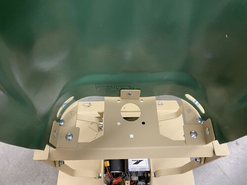
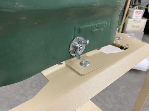
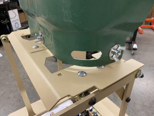
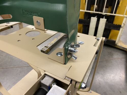
In order to mount an Ivan target, you will need several parts. You will need the three right angle clamps, six carriage bolts, six wing nuts, and three washers. First install one clamp in the center hole of the pivot deck using one carriage bolts and one wing nut. Similarly, install one clamp in holes on the right and left sides of the pivot deck. Now you can install the Ivan target using carriage bolts washers and wing nuts. You will probably need to rotate these two clamps to a roughly 45° angle in order for the plastic to fit properly.
Watch video
Attaching sensors
Bullet hit detection is accomplished with vibration sensors. While these sensors are considered a consumable item, they can be reused if handled carefully. You will need some double-sided tape such as scotch yellow label which is available at most office supply stores. You can also use double-sided foam tape if it's not too thick. Scotch yellow tape will likely give you more signal. Apply a piece of tape to the sensor and attach it to the backside of the target. Position the sensor away from the clamps. The function of the sensor is to detect vibrations in the plastic. The target plastic will not vibrate next to the clamps because it's much more rigid. Connect wires to the sensor connections on the terminal block. Once you have done this, you should check the sensors functionality using the sensor test screen in the control pendant. More on this later. You should use some duct tape on the wires on the plastic target as a strain relief and use some tape to hold the wires away from moving parts. When the target needs to be replaced, very carefully remove the sensor from the back of the target. Try not to pull on the wires when you do this. Once you have removed it, you can reuse it on a new target.
Watch video
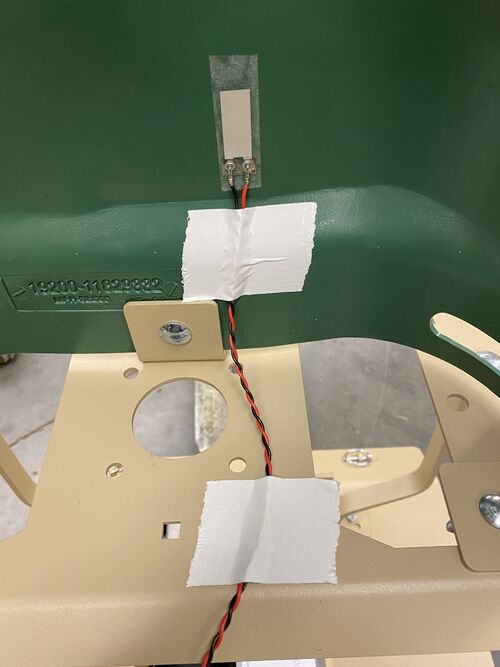
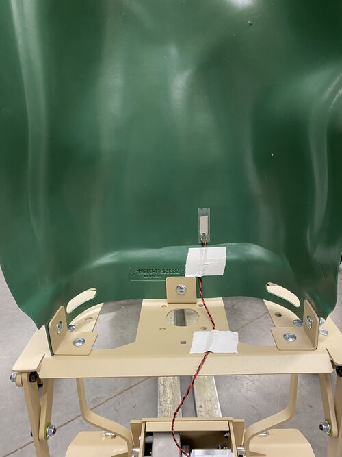
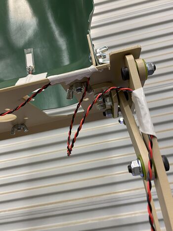
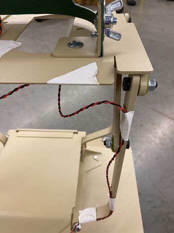
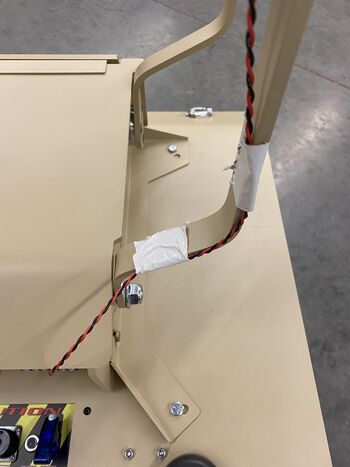
If you are using Hannibal mounted on a TRACS Robot, you need to attach the wires with duct tape to the pivot deck and a rear arm as shown. This is necessary in order to prevent vibration of the wires from generating false hit signals. It's best to attached the wires when the target is collapsed. There must be enough slack in the wire at the pivot deck point and the bottom of the rear arm so that when the mechanism raises and lowers, the wires don't get pulled.
Batteries and charging
The Hannibal reactive target system uses a quick-change lithium polymer battery. The battery charger is designed to be as simple to use as possible. First and foremost, never pull the wires themselves. Always pull the connector housings only. Lithium polymer battery packs are made up of individual cells. In this case there are four cells in the pack. The individual cells need to be balanced during charging. The smart charger will take care of this balance process. The balance connector is the white plastic connector on the battery. This connector needs to be plugged into the corresponding socket on the charger.
Some charger models require you to connect the main battery connector to it as well as the balance plug. The main power connection of the battery is plugged into the corresponding charge cable which is plugged into the barrel connectors on the charger. Make sure you plug the red to red and black to black. There is a charge current knob on the charger and this knob should be turned fully clockwise for fastest charge speed. When you apply power to the charger, before the LEDs will blink red. Press the charge button. The LEDs will light up slightly orange. When charges complete, the LEDs will turn green. This process might take several hours.
More recent charger models only require you to connect the balance plug. This charger type has four blue LEDs indicating the state of charge.
It's important to not leave a charging battery unattended. It's also very important to charge the battery after using it. Always disconnect the battery from the target system after you're finished using it.
To connect the battery, open the cover on the basis of the unit by unscrewing the knob holding the cover in place. Make sure the power switch is turned off and then plug in the battery to the red connector making sure that the wire colors match. The battery rests on top of the motor. To disconnect the battery, grasped the red plastic connector housings and gently pull apart.
Lastly, batteries should always be at least partially charged after using the system. Ideally, batteries stored at 50% charge last much longer than ones that are stored fully empty or full.
Watch video
Power up
On Hannibal 2 units, the tri-color LED on the terminal block will indicate several stages of the boot process. Approximately 15 seconds after the power switch is turned on, the LED will be solid red. At approximately 40 seconds after the power switch is turned on, the LED will blink red. At approximately 45 seconds, the LED will cycle through all of the different colors. Finally, between 50 and 60 seconds, the system will be up and running. If the speaker is connected and powered, you will hear "System operational".
At this point, you can connect your phone to the Wifi Direct and launch the HRTCommander app.
External devices
Hannibal 2 - Using the HRTCommander Mobile App
This section only applies to Hannibal 2.
In order to configure and control Hannibal 2, you will need to use the HRTCommander mobile app. The app is free from the Apple App Store or the Google Play Store.
When powered up, each Hannibal 2 has its own Wifi Direct hot spot that broadcasts a unique SSID.
On the label for inside is a QR Code which you can scan to allow your mobile device to automatically connect.
Once connected, you can configure and control that specific Hannibal target. It's not necessary for your mobile device to remain connected while you're using it when Hannibal is configured for automatic operation e.g. auto-resetting the target.
This video shows the QR Code scanning to connect process:
Scan to connect
The Main Screen
The Main Screen allows you to select a specific Hannibal target if you have several on a standard 802.11 Wifi network. Any Hannibal targets that the app finds on the network are listed in the drop-down menu at the top. If you are connected to the Hannibal's internal Wifi Direct hot spot, you'll only see that one in the menu. In the upper left corner is the menu to bring up the various configuration screens. The menu in the upper right corner has an option to show the GPS coordinate of the mobile device for mapping purposes. Below this is a connection status indicator. When the app is connected and receiving telemetry from the target, a series of animated blue dots will appear. When the app loses connection, this status indicator turns red.
The next section shows the telemetry data from the target including battery voltage, the amp load, the approximate ampere-hours expended, the internal temperature, the status of both hit sensors, the current position of the target, and the state of the external input.
Several buttons are available to raise and lower the target, play a taunting or ambient sound on the external speaker, enable the bobbing feature, and run a scenario.
Hit Sensor 1 & 2 configuration
Hannibal supports two independent hit sensors. Each has its own configuration screen which you access from the menu in the upper left corner of the app.
Electronic noise may be present in the environment that you are operating the Hannibal target. This noise can come from fluorescent lights, radio transmissions, or other electronics. You can filter out this noise by setting the Noise Filter value. In general, you probably won't need to change this value from its default setting. Note that increasing this setting will also filter out impact signals from small bullet hits or edge hits.
The Hit Threshold value tells the system how strong an impact needs to be before it's considered a hit. Larger and slower caliber rounds will generate a stronger impact signal. Small, very high velocity rounds such as 5.56mm are the most difficult to detect.
At the bottom of this screen is a testing section. Here you can sample the baseline noise present in the environment by tapping on the Measure Sensor Noise button. The result will appear as Noise Average and Noise Peak. It's best to set the Noise Filter value higher than the Noise Peak. The strength of impacts is displayed in the Signal Strength and Peak values. The best way to set an appropriate hit threshold is to watch this screen while shooting a few rounds at the target. Note that the hit sensor is detecting vibration from the bullets passing through the plastic target. As the target gets larger holes in it, bullets may pass through a hole and can't be detected. You'll need to replace the target in this case.
The Hits Per Kill section allows you to set a specific number or range of hits that the system registers as a kill. When the minimum and maximum values are the same, every time the target resets, that number is the number of hits required for a kill. When they are different, every time the target resets a new random number in that range is required. This is useful in training to discourage anticipation of the target dropping. It's possible to set these values to zero in which case the target will never drop. However, the external output and audio will still be activated.
In the Effects section, you can enable the Flinching feature which is a non-fatal hit response. You can also configure the choice of sound played on the external speaker for hits or kills and you can set the drop speed of a kill in number of seconds.
Target Lift
Target Lifting is what happens when the target resets to the standing position. The first setting is the Target Lift Mode. This can be set to Automatic or External Input. When set to Automatic, the target will automatically raise when the time specified by the Auto Lift Delay Time has elapsed. When set to External Input, the system looks for a "switch" connected to the Ext. In terminal and the Gnd terminal on the Terminal Block to close. For example, a wireless remote triggered by the instructor. The second and third setting specify the number of seconds of delay before the target is raised when in Auto mode. When the two numbers are different, a new random delay is chosen each time the target raises. Again, the benefit here is to prevent the student from anticipating when the target will do something. You can set a Lift Sound choice for added realism and you can set the number of seconds it takes to raise the target with the Lift Speed setting.
External I/O
An example of an External Input device might be a pressure pad on the floor. The target could be positioned in a room behind a desk or sofa and the pressure pad placed in the doorway. When the student enters the room, the target can pop up from behind cover. The External Input has three settings. First is the Action. Action is what happens when the External Input is triggered. The target can Raise, Lower, Raise/Lower or do nothing. In the Raise/Lower mode, triggering the External Input will drop the target if it's up and raise it if it's down. In the None mode, the External Input can still be used to trigger the Taunting sound system (see below).
The External Input Delay Time sets the number of seconds or a random time before executing the action. For example, entering the room, stepping on the pressure pad but the target may wait a second or two before popping up so as to surprise the student.
On the Hannibal terminal block is a screw labeled "Ext. Out". This is a digital output line that can be used to control external devices in response to hit shots and/or kill shots on either sensor channel. The first setting determines which of the sensor channels will trigger the digital output, Channel (Sensor) 1, Channel 2, or both. The second setting determines under what condition the digital output is triggered: On hits, On kills, On both, or neither. The third setting specifies what the default logic state of the digital output is: Normally On or Normally Off. The choice to use will depend on the type of device you want to control The fourth setting sets a delay time for triggering the external output. The fifth setting sets the length of the logic pulse.
Some examples of External Output devices might be a simple strobe light or a suicide vest simulator. It is also possible to trigger additional Hannibal targets.
Bobbing
The Bobbing feature is intended to simulate the movement of a person on a boat. The first setting turns bobbing mode on and off. When it's on, bobbing can be activated from the main screen of the app or the target must be dropped and raised by a hit and a reset event in order to activate the bobbing for the next evolution. The bobbing behavior can either be randomized or be a consistent amount. The bob period setting is the time in seconds that the target moves up and down in. The last setting determines how far down the bottom of the bobbing movement will be.
Taunting
The Taunting system makes use of the external speaker for added realism. It can be used to entice the student into a shoot/no-shoot situation. The first setting determines what event will trigger the sound. A periodic timer can be used, an External Input device, or both. The second setting determines the sound choice. If Periodic or Both taunting mode is specified, a time specified by the Taunt period (in minutes and seconds) is chosen at random and the sound will play when that timer elapses.
Scenario
Hannibal has a Scenario mode that's intended for use in a shoot house environment. When activated, the system will set a default position for the target and then periodically play sounds intended to distract and make the student anxious. In a typical shoot house situation, students often take their time clearing rooms and move methodically through the building. By introducing sound to the environment, you can challenge the student in new ways. The first setting determines whether the target is standing or crouched down (behind cover) when the scenario begins. The second setting determines the action taken when an external input device e.g. pressure pad is triggered. You can also enable taunting and ambient sound playback and ambient sound timing can be set as desired.
Once you have configured Scenario mode, you can activate the scenario from the main screen of the app or by pressing and holding the button on the terminal block for several seconds. The system will play "Scenario Activated" to let you know that the scenario has begun. Pressing and holding the button again for several seconds will deactivate the scenario and the system will play "Scenario completed".
Hannibal Gen 1 - Using the Configuration Pendant
This section only applies to Hannibal Gen 1.
The configuration pendant included with the product allows you to change the various settings in the software. Inside the Hannibal target you will see the brain box mounted on the right (when viewed from the rear). There are two covered connectors. One is a standard RJ-45 Ethernet connector and the other is a Type-A USB connector. Plugging the configuration pendant into the connector will power up the pendant when the main power switch is turned on (with a battery installed).
The "Splash" screen will be displayed when you plug it in and it will show the version number of the software.

The six buttons on the pendant allow you to navigation the configuration menus, modify settings, and issue certain commands to the system.
The green check button is typically used to accept or save a change to a particular setting.
The red X button will cancel a setting change in progress. This button will also exit out of a setting menu and return to the main menu. From the main menu, pressing this button will return to the splash screen.
The up and down arrows typically are used to scroll through menus or settings within a menu. The left and right arrows will typically change the value of a given setting.
Note: please read the documentation carefully for situations where the buttons are used for other purposes e.g. raising/lowering the target.
Watch video
Menu Shortcuts
When the Splash Screen is displayed, there are two menu shortcuts available.
Pressing the Up arrow will put the system into a sensor monitor and test mode and display a screen accordingly.
Pressing the Down arrow will jump to the System Monitor screen where you can view the battery status, hit/kill counts, last hit sensor values, etc.
Watch video
Sensor Monitor Mode

The Sensor Monitor screen & mode allow you to test the sensors without the target moving. In this mode, you can hit the target and see how the sensor is responding. In this way, you can also easily see what happens when you mount the sensor in different locations and with different mounting tapes.
This mode also allows you to view how electrical noise in the environment is affecting the sensors. Electrical noise can come from two-way radios, fluorescent lighting, DC motors, etc.
You can command the system to sample the noise by pressing the right arrow button without hitting the target. When you do this, you may see the noise numbers change.
An electrically "quiet" environment will result in fairly low noise numbers e.g. less than 50. If there is a lot of noise, it's possible that the wires or the sensor itself are damaged.
Watch Video
System Monitor Mode
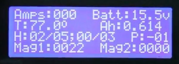
The System Monitor screen & mode gives you the ability to see the current system status and control the target manually.
In the upper left corner, you will see Amps. This shows the current draw of the motor drive when it's moving. This can be helpful in determining if the mechanical parts are working well and how much power the system is drawing if you're using different kinds of targets.
Batt: shows you the battery voltage reading. Hannibal batteries range from 16.8 volts when fully charged to 14.4 volts when exhausted. Note that the battery voltage is only a rough estimate of the "state of charge". The voltage does not drop off in a linear manner during usage. Initially, the voltage will drop quickly. Then it drops slowly over the majority of the capacity usage. As the "state of charge" reaches what can be considered "empty", the voltage drops off quickly again.
The second line of the display shows the system temperature and a rough estimate of how many ampere-hours have been consumed during operation. The temperature will rise with heavy and/or frequency raising/lowering of the target. The Ah (ampere-hour) value can give you an idea of how much time you have left on the battery. Hannibal batteries are 6.0 Ah in size. When the displayed Ah value is 3.0, for example, roughly half of the battery's capacity has been used. Note: the system doesn't remember this value so it's only useful on a fully charged battery and only as long as the power switch is on.
The third line shows the current hit/kill values for both sensors and the "position" of the mechanism.
The fourth line shows the magnitude of the last hit on each sensor.
Watch video
Sensor Menus
Hannibal supports two independent hit sensors. Each can be configured independently. It is not necessary to connect a sensor device if you don't want to use both of them.
Dropping into the menu for Sensor 1 or Sensor 2 shows the following three sub-menus:
Sensitivity Screen
In this screen, you can configure the hit sensor. The sensor system is really measuring the change in the flex of the sensor from one moment to the next. If you imagine a drum head or a guitar string, the drum or string vibrates when you hit it. The same behavior is happening to the hit sensor although you can't hear it or even see it.
When this screen is displayed, the mechanism won't move so that you can test the hit sensor and adjust the settings. The system will play the hit sounds if the speaker is connected and turned on.
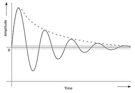
The above image illustrates what the sensor system is seeing when the target is hit. The grey band represents electrical noise that the sensor might be experiencing from things like radio transmitters, bad fluorescent lighting, poorly made vacuum cleaners, etc. Picture what you might hear on an AM radio when a motor is running nearby.
The Noise Filter setting allows the system to ignore the noise while allowing for the actual hit signal to pass through. If you are familiar with Ham or CB radios, the Noise Filter is similar to Squelch. If you set squelch on a CB radio too low, you hear static. If it's too high, you might miss weaker radio transmissions.
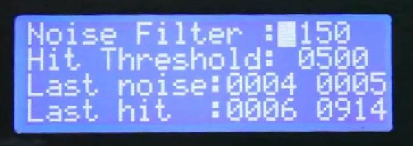
To adjust the Noise Filter value, use the up/down arrows to position the cursor on the Noise Filter line. Then press the right arrow to increase the value and the left arrow to decrease it. Pressing and holding the left/right arrows will change the setting quickly and in a repeating fashion. The Hit threshold value can be changed in the same manner by positioning the cursor on the second line.
If you move the cursor with the up/down arrows to the third line and press the right arrow button, the system will sample the noise and update the display. In this way, you can get a good idea what value to use for the noise filter. The "Last noise" values that are displayed are the average noise and the peak noise. The Noise filter value needs to be set above the peak noise reading. It's a good idea to set it higher just in case some stray electrical noise inadvertently triggers a false hit.
Referring back to the above image, the oscillating wave is what the system sees after passing through the Noise Filter. The top of the first wave is the Peak Value. This value is displayed on the fourth line on the right side. The system evaluates the signal and counts the number of times the amplitude is above the Hit Threshold. This count is shown on the first number of the fourth line.
Different bullet sizes and velocities will result in different sensor readings. This is further affected by how many rounds the target has taken. A new target will always work better than one that's had a few hundred bullet holes in it.
The sensor readings for head shots will be lower than for body shots (for the same sensor location).
How the sensor is mounted will also affect the system. Positioning the sensor next to the L-bracket will likely prevent the sensor from picking up a hit.
You can also partially tape the sensor at the wired end and leave the opposite end free in order to get more of the vibration. Picture a swimming pool diving board that's fixed at one end.
Watch video
Hit Menu
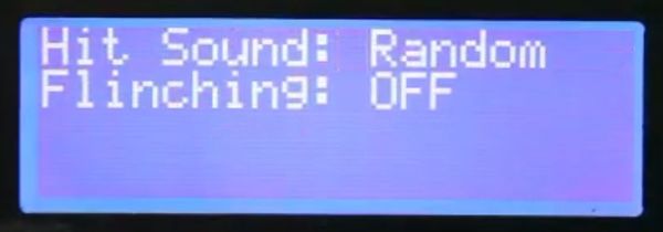
The Hit menu has two simple settings. First is the sound choice. There are ten sounds available. You can also set it to Random or Off.
The second settings is Flinching or a non-fatal hit response. When this feature is turned on and a hit is detected such that the hit counter is less than the kill shot count, the mechanism will cause the target to flinch. This can be useful in a training situation to encourage the student to keep shooting until the target goes down completely.
Watch video
Kill Menu
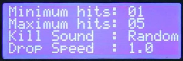
The Kill menu has four settings in it. The first two are the minimum and maximum number of hits necessary to register a kill. When these two numbers are different, the system will choose a new number of hits to be considered a kill each time the target is raised. This is useful in a training situation to get students out of the habit of expecting the target to go down after, say, two rounds to center mass.
By setting these to zero, you can prevent the target from dropping entirely. Hits will still trigger the sounds and/or the flinching feature if those are active.
The third setting selects the sound played after the kill shot has been detected. This can also be random or deactivated as desired.
The fourth setting controls how fast the target will drop when killed. The value is in seconds.
Target Lift Menu
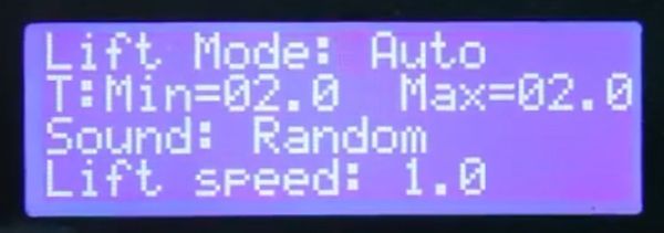
Target Lifting is what happens when the target resets to the standing position.
The Target Lift menu has five settings. The first is the Lift Mode. This can be set to Auto or Ext. In. When set to Auto, the target will automatically raise when the time specified by the two settings on the second line has elapsed.
When set to Ext. In, the system looks for a "switch" connected to the Ext. In terminal and the Gnd terminal on the Terminal Block to close. For example, a wireless remote triggered by the instructor.
The second and third setting specify the number of seconds of delay before the target is raised when in Auto mode. When the two numbers are different, a new random delay is chosen each time the target raises. Again, the benefit here is to prevent the student from anticipating when the target will do something.
The fourth setting determines the lift sound choice for added realism.
The fifth setting determines the number of seconds it takes to raise the target.
Watch video
External Input Menu
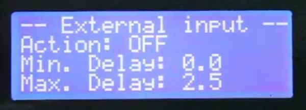
An example of an External Input device might be a pressure pad on the floor. The target could be positioned in a room behind a desk or sofa and the pressure pad placed in the doorway. When the student enters the room, the target can pop up from behind cover.
The External Input menu has three settings. First is the Action. Action is what happens when the External Input is triggered. The target can Raise, Lower, Raise/Lower or do nothing. In the Raise/Lower mode, triggering the External Input will drop the target if it's up and raise it if it's down. In the None mode, the External Input can still be used to trigger the Taunting sound system (see below).
The second and third setting are for time delay of the action. For example, entering the room, stepping on the pressure pad but the target may wait a second or two before popping up so as to surprise the student.
Watch video
External Output Menu
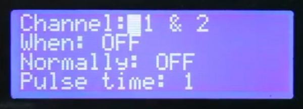
On the Hannibal terminal block is a screw labeled "Ext. Out". This is a digital output line that can be used to control external devices in response to hit shots and/or kill shots on either sensor channel.
The first setting determines which of the sensor channels will trigger the digital output, Channel (Sensor) 1, Channel 2, or both.
The second setting determines under what condition the digital output is triggered: On hits, On kills, On both, or neither.
The third setting specifies what the default logic state of the digital output is: Normally On or Normally Off. The choice to use will depend on the type of device you want to control
The fourth setting sets the length of the logic pulse.
Some examples of External Output devices might be a simple strobe light or a suicide vest simulator. It is also possible to trigger additional Hannibal targets.
Watch video
Taunting Menu
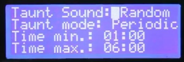
The Taunting system makes use of the external speaker for added realism. It can be used to entice the student into a shoot/no-shoot situation.
The first setting determines the sound choice.
The second setting determines what event will trigger the sound. A periodic timer can be used, an External Input device, or both.
If Periodic or Both is specified, a time between the third and fourth settings (in minutes and seconds) is chosen at random.
Watch video
Bobbing Menu
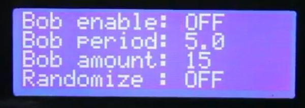
The Bobbing feature is intended to simulate the movement of a person on a boat.
The first setting turns bobbing mode on and off. When it's on, the target must be dropped and raised by a hit and an reset event in order to activate the bobbing for the next evolution.
The second setting is the time in seconds that the target moves up and down in.
The third setting determines how far down the bottom of the bobbing movement will be.
The fourth setting allows you to randomize the amplitude of the bobbing for additional realism
Watch video
Scenario Menu
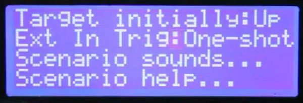
Hannibal has a Scenario mode that's intended for use in a shoot house environment. When activated, the system will set a default position for the target and then periodically play sounds intended to distract and make the student anxious. In a typical shoot house situation, students often take their time clearing rooms and move methodically through the building. By introducing sound to the environment, you can challenge the student in new ways.
The first setting determines whether the target is standing or crouched down (behind cover) when the scenario begins.
The second setting determines the action taken when an external input device e.g. pressure pad is triggered.
A sub-menu allows you to configure the sounds being used and when they are played.
Once you have configured Scenario mode, you can activate the scenario by pressing and holding the button on the terminal block for several seconds. The system will play "Scenario Activated" to let you know that the scenario has begun. Pressing and holding the button again for several seconds will deactivate the scenario and the system will play "Scenario completed".
Watch video
Network Settings Menu
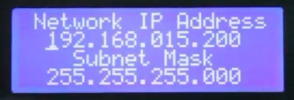
The Network Settings menu allows you to change the static IP address and netmask for the Ethernet port.
Watch video
